MACS Matchmaker
Molographic chips are the consumable at the heart of every MACS Matchmaker measurement. This page covers the available chip types and how to pick one, the immobilization strategies for attaching your ligand, multiplexing options, chip handling and assembly, and the manual preparation workflow for coupling and XY-stage adjustment.
Sensor Chips
The Focal Molography sensor chips are made from glass covered with a waveguide. The chips have an incoupling grating on both short sides and are asymmetrical: one side carries a Lino Biotech logo and a chip ID. Chips come in a standard 8 × 8 layout of 64 molograms. Each mologram has pre-functionalized ridges and grooves that can be functionalized either for direct ligand immobilization via click chemistry or via DNA-directed immobilization.
Each chip carries 64 molograms arranged in an 8 × 8 grid, named SM_RxCy (row x, column y).
Chip Types
Two main chip types are available:
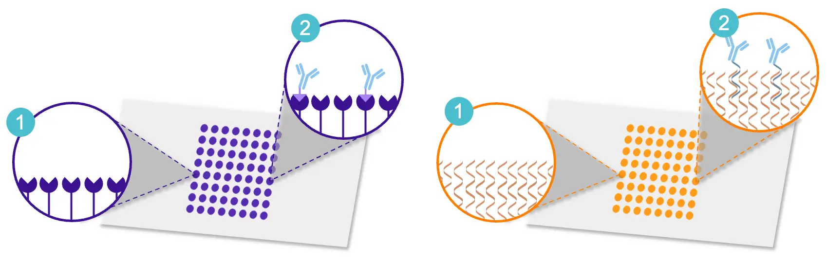
- Click Chemistry Chips (left). Functionalized with tetrazine (Tz) or methyltetrazine (Me-Tz) groups for covalent immobilization of TCO-modified biomolecules via bioorthogonal click chemistry. Robust and covalent, with a 2D PEG layer that keeps NSB low. Ideal when ligand is scarce, but each new target usually needs its own regeneration protocol.
- DNA-Directed Immobilization (DDI) Chips (right). Functionalized with 20-mer single-stranded DNA oligos in predefined patterns, enabling multiplexed and versatile target immobilization. Easily regenerable: the DNA can be dehybridized and a new conjugate applied — usually without bespoke regeneration conditions. A range of oligo adapters and protein–DNA conjugation kits is available on the Lino Biotech webshop.
What the surface looks like
The chip name states what sits on the ridges and what sits in the grooves. The ridges carry the binding chemistry; the grooves carry whatever the variant passivates them with, and it is the difference between the two that the coherent channel reads.
Chip Selection Guide
Pick by regenerability and sample matrix. Complex media refers to samples with high background protein content — serum, plasma, cell lysate, conditioned media — where unspecific binding can be actively suppressed by a matched backfill. Buffered samples and purified proteins in defined buffer count as simple media. The table below maps each combination to the recommended sensor product.
| Simple Media / Buffer | Complex Media (serum, plasma, cell lysate) | |
|---|---|---|
| Regenerable | [Oligo|PEG] Non-backfilled oligo | [Oligo|Oligo] Backfilled oligo |
| Non-regenerable* | [Me-Tz|PEG] Non-backfilled click chemistry [Tz|PEG] (planned) The same surface with the faster tetrazine on the ridges, which couples at a lower ligand concentration | [Me-Tz|Tz] Backfilled click chemistry |
* Non-regenerable means the ligand cannot be released: it is coupled covalently, so the chip cannot be stripped and reloaded with a different ligand. The chip can still be reused across cycles by regenerating the ligand itself — stripping the analyte and leaving the ligand active — but that condition is specific to the pair and has to be scouted.
Surface Functionalization
After every immobilization (all strategies): flush the chip surface with at least 1 mL of running buffer (e.g. 3 min at 300 µL/min or 5 min at 200 µL/min) before continuing. The flush carries away ligand that is adsorbed rather than coupled — material sitting on the surface without a duplex or a covalent bond holding it there. Left in place it comes off slowly during the measurement and reads as drift.
Click-Chemistry Passivation
Click-chemistry strategies (TCO–Me-Tz, TCO–Tz) require an extra passivation step before the post-immobilization flush: cap residual Me-Tz/Tz groups with 100 µM TCO-PEG₄-OH for 5 min at 20 µL/min, then flush as described above. Skipping passivation leaves reactive groups on the surface that can scavenge later analyte and produce drift.
Immobilization via DDI Strategy
For flow rate and duration, see the Immobilization (DDI) row in Recommended Flow Parameters.
- DNA or protein–DNA conjugate concentration: 200 nM, whether the conjugate comes from a conjugation kit or from chromatographic purification.
- Lower concentrations (e.g. 50 nM) may give insufficient ligand density and a weak signal.
- To tune ligand density, mix the Molo-Adaptor strand with the DNA-conjugated protein in the chosen molar ratio, shorten the immobilization time, or use a stop condition. For target densities per assay type, see Ligand Density vs. Mass Transport Trade-Off.
- Tip: use the Immobilization phase template in Experiment Design.
Immobilization via TCO Click Chemistry
For flow rate and duration, see the Immobilization (TCO–Me-Tz / TCO–Tz) row in Recommended Flow Parameters. The ligand carries a TCO group and clicks onto the tetrazine on the ridges. Which tetrazine that is depends on the sensor, and it sets the concentration to inject: the unsubstituted tetrazine of [Tz|PEG] reacts faster than the methyltetrazine of the Me-Tz sensors, so it couples from a lower concentration.
| Ridge chemistry | Sensor | Ligand-TCO concentration |
|---|---|---|
| Me-Tz (TCO–Me-Tz) | [Me-Tz|PEG], [Me-Tz|Tz] | ≥ 10 µM |
| Tz (TCO–Tz) | [Tz|PEG] (planned) | ≥ 1 µM |
Below these, the ligand density is generally too low and the signal correspondingly weak: on this surface 200 nM gives insufficient loading. Establish the minimum for the ligand and target response you actually use. To tune density downwards on purpose, mix active and non-binding variants in known molar ratios instead of diluting the active one; a 1:1 mixture is nominally 50% active in the injected mixture, and the resulting surface should be verified against its response rather than assumed.
Affinity Matching (Frontfilling and Backfilling)
Frontfilling immobilizes the specific ligand on the ridges; backfilling immobilizes a chemically similar, non-active molecule in the grooves. For the FM principle and the role of affinity matching in NSB suppression, see Backfilling and NSB suppression.
Chip-preparation guidance: the backfilling immobilization level is the most critical parameter to achieve chemical uniformity — it should match the frontfilling level. For DDI-based assays, the Oligonucleotide strand 00 is always used for backfilling.
Verify the match before measuring: inject the blank sample matrix (no analyte) and confirm the CMD baseline stays flat — the refractometric MD channel is expected to rise as the surface fouls. A CMD baseline that climbs on a matrix-only injection signals a ridge–groove mismatch; raise or lower the backfill level to match the frontfill. See Verifying backfill quality.
Multiplexing
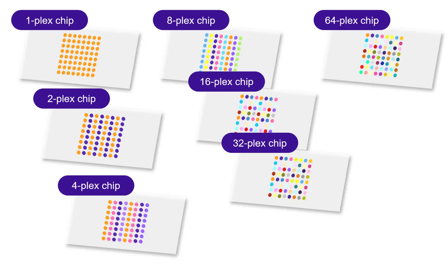
Multiplexing is exclusively available on DNA-Directed Immobilization (DDI) chips and enables simultaneous analysis of multiple interactions on the same chip. DDI chips are available in pre-multiplexed formats from 1-plex up to 64-plex — different molograms on the chip carry distinct oligonucleotide sequences, allowing immobilization of up to 64 different ligands on a single chip. Higher plex counts trade replicates for ligand diversity: each group should ideally keep enough molograms to support the statistical power required by the assay (typically ≥ 2 replicates per group). Sequences run from Seq ID 01 to 64 (00 is the backfill strand); 32-plex is the usual choice, leaving molograms for replicates of each ligand. Backfill assignment is covered in Surface Functionalization.
Multiplexed chips are available in two surface chemistries:
- [Oligo|PEG] — non-backfilled oligo chips for simple media (buffer). 1-plex to 64-plex. See oligo | PEG sensors.
- [Oligo|Oligo] — backfilled oligo chips for complex media (serum, plasma, cell lysate). 1-plex to 64-plex. See oligo | oligo sensors.
How Multiplexing Works
- Each multiplexing group on the chip contains molograms with a unique surface oligonucleotide sequence. To immobilize a ligand on a specific group, its complementary DNA strand must be conjugated or ligated to the ligand prior to immobilization.
- Ensure similar immobilization chemistry and surface densities across groups for quantitative comparability.
- Use a stable, covalent attachment (DDI conjugate or click); avoid dissociable adapters such as His-tag / trisNTA, whose released ligand can rebind a neighbouring group and cross-contaminate plexes.
- The multiplexing layout is configured during experiment design in the software: pick a multiplexing format and assign ligands to groups.
Multiplexing Layouts
The maps below show the oligo group assignment for each plex configuration on the 8 × 8 chip — molograms sharing a color carry the same surface oligonucleotide and accept the same complementary adapter. The same maps drive the analysis per ligand in the insights.
Chip Handling
The following guidelines help ensure optimal chip performance and longevity:
- Always handle chips by the edges (where the Lino logo is) to avoid contaminating the active surface.
- Store chips dry at 4°C (or alternatively at room temperature) in a clean environment away from direct sunlight. Do not freeze and do not store chips submerged in liquid — both significantly reduce chip lifetime. Shelf life is 12 months from the date of manufacture under recommended conditions. Check the expiration date on the chip Certificate of Analysis before use.
- Avoid touching the waveguide surface to prevent damage or residue buildup.
- Use gloves to minimize oil and dirt transfer.
- Rinse chips with deionized water and dry with a nitrogen stream.
Chip Assembly
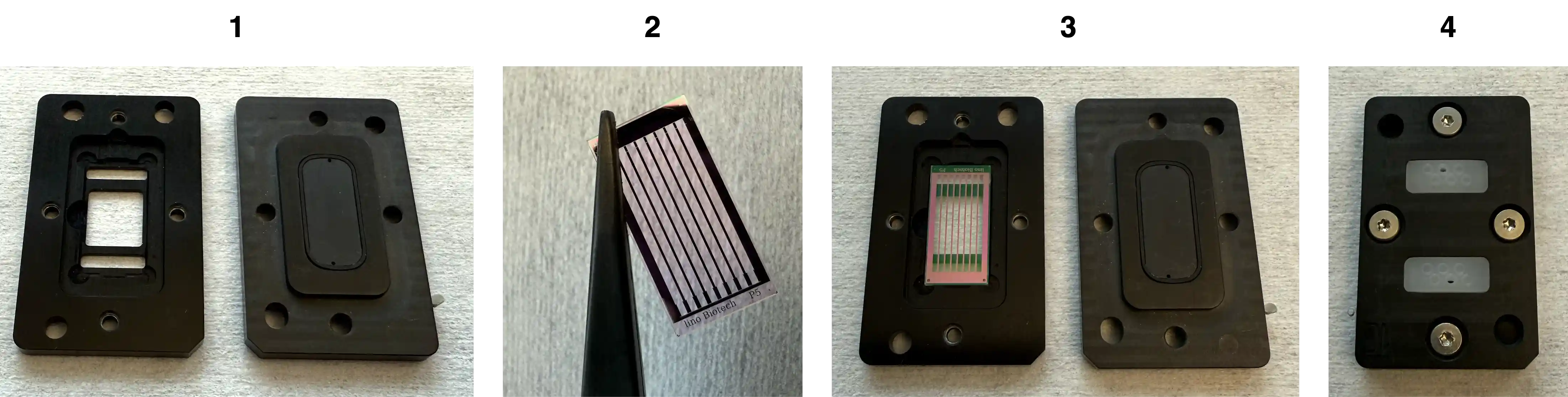
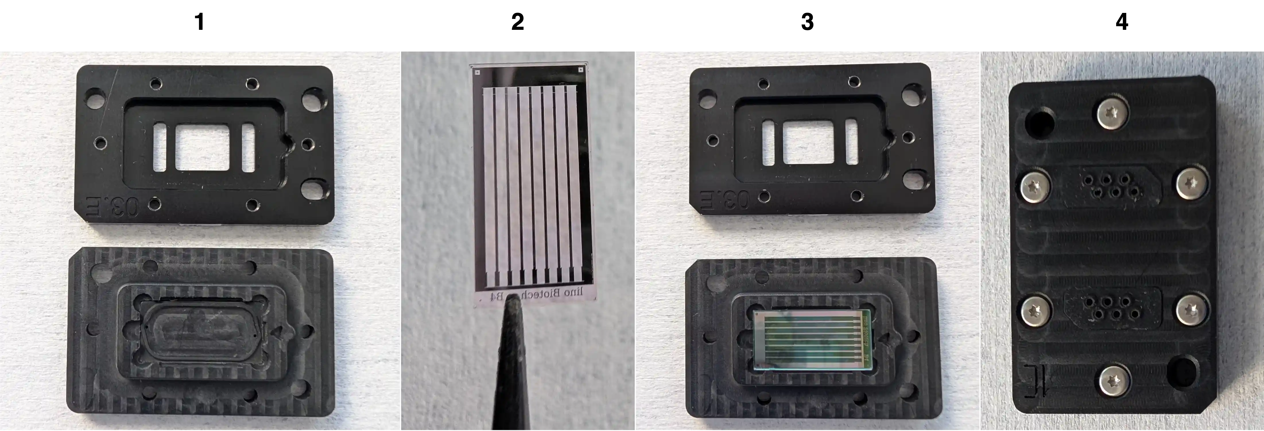
The MACS Matchmaker ships with two flow-chamber families that differ in how the chip is mounted: a 4-screw design (chip dropped into the chamber and held by a top lid) and a 6-screw design (chip seated face-down into the top part and clamped from below). The two procedures are described separately below.
Both designs use the same chip orientation reference: the Lino Biotech logo identifies the front face of the chip, and the triangle marker on the chip edge indicates the side that aligns with the matching triangle on the flow chamber.
4-Screw Flow Chamber Assembly
- Prepare the flow chamber by cleaning it with appropriate solvents (IPA, MQ) and drying it thoroughly. Handle solvents per the lab safety rules in Safety & Compliance.
- Place the chip into the designated slot in the flow chamber with the Lino logo facing upwards and the triangle marker aligned with the chamber triangle.
- Place the lid on top of the flow chamber, ensuring it aligns properly with the chip.
- Secure the lid using the four provided screws. Tighten evenly in a cross pattern — finger-tight — to avoid gaps or asymmetric pressure.
6-Screw Flow Chamber Assembly
- Prepare the flow chamber by cleaning it with appropriate solvents (IPA, MQ) and drying it thoroughly.
- Place the chip into the top part of the flow chamber with the Lino logo facing downwards (functionalized face toward the channels) and the triangle marker aligned with the chamber triangle.
- Close the chamber and by putting the bottom part on top of the top part, ensuring it aligns properly with the chip and the top part.
- Secure the chamber with the six screws. Tighten evenly in a cross / star pattern — finger-tight — to distribute gasket pressure uniformly.
Flow Chamber Layouts
The following flow chamber layouts are available, each compatible with the same chip but offering different channel configurations to suit various assay needs.
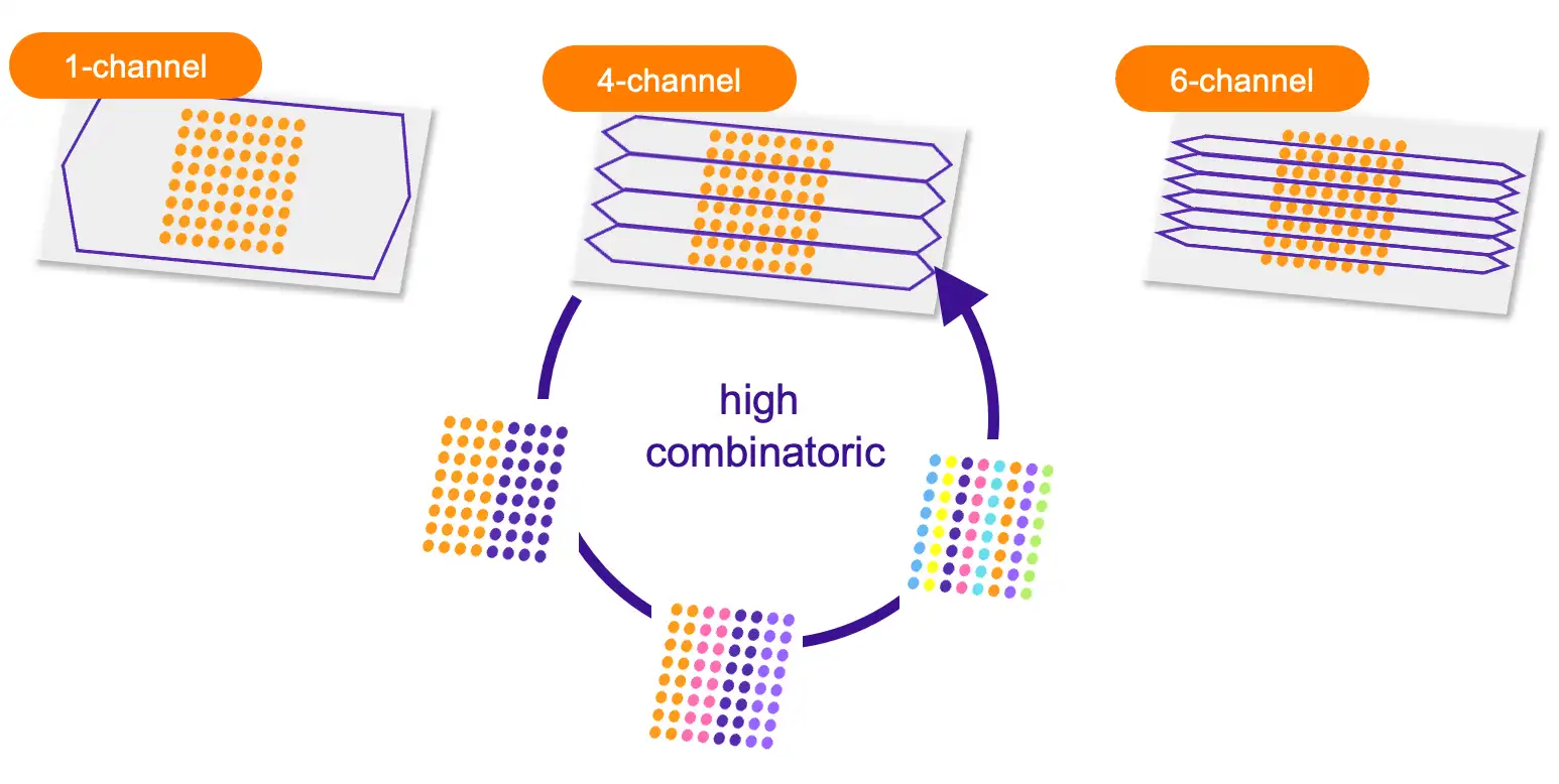
Note: in multi-channel flow-chamber formats, the sealing gasket covers the mologram rows between channels. Once a chip has been used in a multi-channel configuration, the rows that were covered by the seal are not guaranteed to be functional anymore due to potential surface damage from gasket contact. Plan chip usage accordingly — if you intend to use all 64 molograms, start with a single-channel flow chamber.
Manual Chip Preparation
The chip can also be prepared manually from the System Control Page.
Chip Coupling
- In the System Control Page, click on "Molo Mirror".
- Either click "Optimize Position" or click the top-right icon to open the coupling camera and couple manually.
- With the coupling camera open, adjust the chip position until the alignment is correct. Use the right-hand controls to change step size and the left-hand controls to adjust the coupling.
- Aim for a coupling that is as bright as possible and uniform / symmetrical.
If Coupling Fails
Work through the coupling attempts in this order — each step uses a more detailed algorithm than the previous one:
- Prime the chip before attempting to couple. A dry or improperly primed chip will not couple reliably.
- If Prepare Reader fails, run coupling from the Instrument Operation page. The Instrument Operation page uses a more detailed coupling algorithm and succeeds in cases where Prepare Reader does not.
- If that still fails, couple manually from the System Control page:
- Open the Molo Mirror card. Make sure the correct Flow Chamber is selected.
- Click Reset and Optimize Position first. This runs the auto-coupling algorithm from the current position and often recovers the coupling once the flow chamber is set correctly.
- If Optimize Position does not succeed, click the image button to open the coupling camera. Use the arrow controls on the left to move the position and the step-size control on the right to change how far each arrow press moves. Start with a larger step size to find the signal, then reduce the step size to refine it.
- Keep adjusting until the coupling is as bright as possible and uniform / symmetrical across the field of view.
- If manual coupling fails, try disassembling and reassembling the chip (see Chip Assembly), ensuring that it is properly seated in the flow chamber and that it is visually clean. Then repeat the coupling process.
XY Stage Adjustment
- On the System Control page, locate the "XY Stage" panel.
- Either click "Optimize Position" or click the top-right icon to open the XY-stage camera and adjust manually.
- With the XY-stage camera open, adjust the chip position until the mologram is centered in the field of view. Select the step size and unit, then use the arrow buttons to move the XY stage. These controls are also available directly in the XY Stage panel.