MACS Matchmaker
Focal molography detects only the coherent mass difference between ridges and grooves. Molecules adsorbing randomly across the entire surface — on ridges and grooves equally — do not alter this difference, and are therefore strongly suppressed in the CMD channel when adsorption is equal on both regions. To keep that baseline flat in crude media, backfilling is essential: immobilizing a chemically similar non-active molecule into the grooves ensures that high-abundance matrix proteins bind equally to both regions, preventing the formation of a coherent non-specific signal.
The quality of backfilling determines whether NSB is sufficiently suppressed for the assay. When ridge and groove chemistry is mismatched (), matrix proteins adsorb preferentially to one region, producing a non-zero coherent NSB response during matrix exposure. Affinity-matched backfilling () equalizes the NSB across both regions so it cancels out, leaving only the specific analyte signal (see Reichmuth et al. 2021).
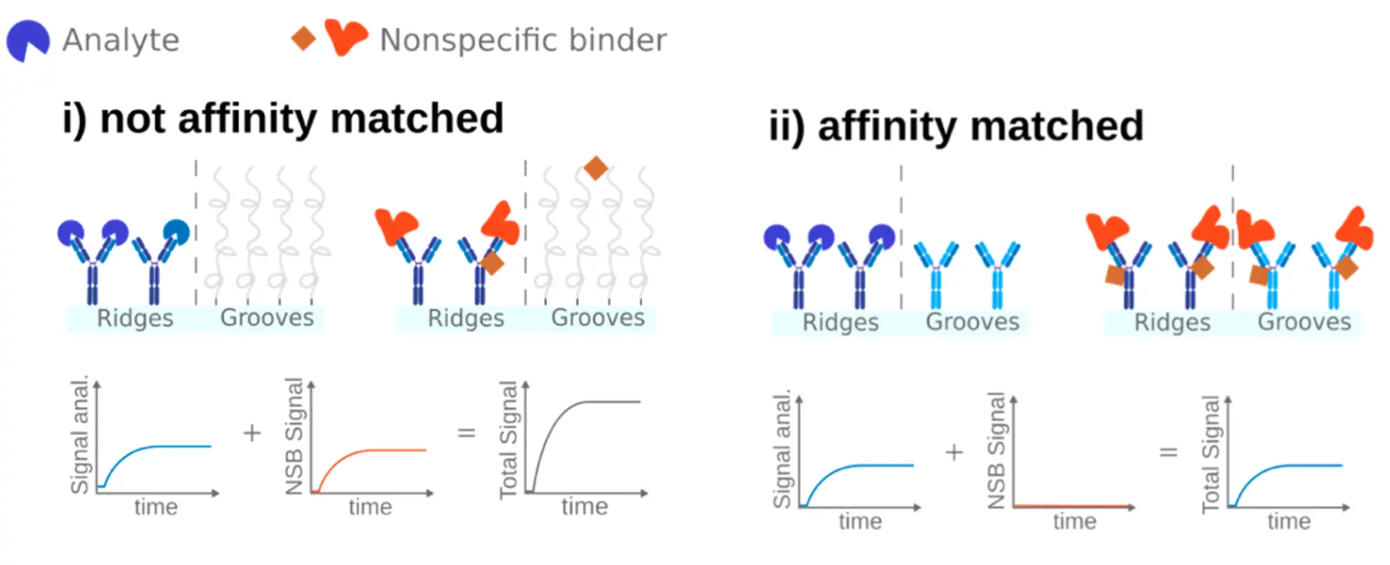
What backfilling actually is
Each mologram is two interspaced sets of lines: ridges and grooves. Loading the chip is therefore two separate immobilization steps on the same surface. Frontfilling attaches your active ligand to the ridges; backfilling attaches a non-target-binding backfill probe to the grooves. The probe is chemically matched so nonspecific binders encounter similar ridge and groove surfaces, while it remains unable to bind the target. Backfilling is not a generic block (it is not the BSA or Tween in your running buffer) and it is not a coating — it is a deliberate, individually addressed immobilization that rebuilds the groove to mirror the ridge.
The two regions are addressed by orthogonal chemistries so they can be filled independently:
- DDI [Oligo|Oligo]: ridges and grooves carry different capture-oligo sequences. You hybridize the ligand–DNA conjugate to the ridge strand (frontfill) and a non-binding conjugate to the groove strand (oligonucleotide strand 00, backfill).
- Click [Me-Tz|Tz]: ridges and grooves bear two orthogonal tetrazine variants that react with TCO-tagged molecules under different conditions, so each region is functionalized on its own.
A useful way to picture the workflow: because CMD reports the coherent difference between ridges and grooves, frontfilling drives the immobilization CMD up (mass added to ridges only), while backfilling drives it back down toward balance (immobilizing the backfill probe in the grooves restores the ridge–groove symmetry). A well-matched chip therefore starts the assay near a balanced state — after which specific analyte binds the ridges and produces signal, while matrix proteins bind both regions equally and cancel. The immobilized level in each region — the surface density read straight off the immobilization CMD — is the quantity you tune.
Backfilling suppresses coherent NSB — it does not prevent fouling
A common misconception is that an affinity-matched chip stays clean in serum. It does not. Matrix proteins still adsorb across the entire surface and can accumulate substantially in undiluted plasma. Backfilling does not stop that adsorption; a well-matched surface aims to make it similar enough on ridges and grooves that the coherent contribution is minimized.
Three things are matched, and they are not the same thing. Equal immobilization CMD says the two regions carry comparable amounts of probe. Matched surface chemistry says the probe presents a similar face to the sample. Only matched non-specific adsorption behavior is what actually suppresses the background — and the first two make it likely rather than certain. That is what the matrix-only injection tests.
The practical consequence: in a crude matrix the refractometric MD channel will still rise steadily while the CMD baseline stays flat. That divergence is the expected, healthy signature of a well-matched chip — not a fault. The fouling is real, however, so cleaning and regeneration are still required (see Maintenance & Troubleshooting).
When backfilling matters
The magnitude of coherent NSB grows with three factors: the affinity mismatch between ridges and grooves, the concentration of the background binder, and its affinity (a lower — i.e. a tighter non-specific binder — is worse). Coherent NSB is therefore most severe in crude, protein-rich matrices such as serum, plasma, and cell lysate, where abundant components sit in the µM–mM range.
In simple media — buffer or purified protein in a defined buffer — uniform adsorption is already negligible in the CMD channel, so backfilling is unnecessary and passivated [Oligo|PEG] or [Me-Tz|PEG] chips suffice. Match the chip to the matrix using the Chip Selection Guide.
Choosing a backfill probe
An effective backfill molecule presents the same adsorption profile to matrix components as the ridge ligand, while never engaging the analyte. In practice it must be:
- Chemically similar to the ridge ligand — matched molecular weight, charge / isoelectric point (pI), and refractive index, so background proteins cannot tell ridges and grooves apart. In the FLAG model system it was the net charge of the epitope that drove the affinity difference, so matching charge is often decisive.
- Non-binding to the analyte — a large affinity difference toward the target relative to the ridge ligand, so the backfill never captures or competes for analyte and the specific signal stays ridge-only.
- Immobilized through an orthogonal but equivalent chemistry, at a density matched to the frontfill level. The two coupling reactions must be independently addressable yet leave chemically indistinguishable surfaces.
- Reproducible — the degree of chemical assimilation must be controllable batch to batch.
Typical realisations: for peptide assays, a sequence-scrambled variant of the active peptide (same composition and charge, no functional epitope); for DDI [Oligo|Oligo] chips, the dedicated backfill strand (oligonucleotide strand 00) carrying a non-active conjugate matched to the ridge ligand; for click chemistry [Me-Tz|Tz] chips, an orthogonal tetrazine reaction in the grooves. Lino's pre-functionalized backfilled chips ([Oligo|Oligo], [Me-Tz|Tz]) ship affinity-matched; for custom ligands the backfill must be designed to the criteria above.
Tuning the backfill level
Backfill level — the immobilization level of the chemically matched, non-binding backfill probe in the grooves — is one of the principal adjustable parameters, alongside probe chemistry, active fraction and matrix compatibility. The target is simple: it must match the frontfill (ridge) level while preserving the affinity-matched ridge and groove surface chemistry.
Ideally, drive both regions into saturation. Keep loading the ridge ligand and the groove backfill until further injection no longer raises the immobilization signal. Saturating both is the most reproducible way to reach a matched surface — both regions sit at their ceiling rather than at a partial, batch-to-batch-variable level — and it gives the largest . Tune the active fraction on the ridges separately by mixing active and non-active probe, not by under-loading the surface.
Follow it on the immobilization trace. Because CMD reports the ridge–groove difference, adding ligand to the ridges (frontfill) raises the displayed CMD response, while immobilizing the backfill probe in the grooves moves it back toward balance; the refractometric MD channel, which sees both regions, keeps rising as total mass is added. The two regions are matched when their levels are equal, which the backfill approaches as it nears the frontfill level. Use the trace as a guide, but confirm the match with a blank-matrix injection (below) rather than relying on the immobilization signal alone.
The knobs are the same ones used to set any immobilization density: the backfill probe concentration, the contact time, the flow rate, and — for fine control — a stop condition on the immobilization phase or mixing active and non-active probe at a fixed molar ratio. For DDI chips the groove address is strand 00, so the level is set by the concentration and contact time of the non-active conjugate on that strand. Concrete flow rates, durations, and concentrations per chemistry are in Surface Functionalization; the density-versus-kinetics trade-off applies to the ridges too (see Ligand surface density).
- Under-filled grooves leave ridges heavier than grooves — residual imbalance, so matrix proteins still raise a coherent NSB signal.
- Over-filled grooves tip the baseline-relative CMD balance the other way and can produce a negative response upon analyte injection. The coherent optical signal itself remains positive, and overfilling does not imply signal instability. Use equality between the groove and ridge immobilization levels as the stop condition; do not continue past it. On the next tuning run, use a lower backfill-probe concentration or a shorter contact time so the groove level reaches, but does not pass, the ridge level.
After tuning, always confirm with a blank-matrix injection before the real measurement (see Verifying backfill quality below).
Backfilling preserves the specific ridge signal
A non-binding, affinity-matched groove probe should not contribute a specific signal. The response and detection limit can still differ from buffer because complex matrices change transport, competition, adsorption, and assay variability. Confirm performance with matrix-matched blanks and calibration samples rather than assuming equivalence.
Verifying backfill quality
To confirm a chip is correctly matched, inject the blank matrix — the sample background without analyte — and watch the CMD baseline. A flat CMD trace (with the MD channel free to rise as the surface fouls) confirms affinity matching. A CMD baseline that climbs on a matrix-only injection indicates a ridge–groove mismatch and predicts coherent NSB during the real measurement.
If the match is imperfect and a residual deflection remains after re-tuning, dilute the sample matrix to 25–50% in running buffer. Diluting lowers the concentration of the abundant matrix proteins that drive non-specific binding, so the coherent NSB shrinks and the CMD baseline flattens — often enough to recover usable data from a not perfectly backfilled chip. The trade-off is that the analyte is diluted by the same factor, so account for it in the concentration and in the expected .
For the broader context of how CMD rejects non-specific binding, see the MACS Matchmaker concept overview. Running assays in serum, plasma, and lysate is covered below.
Measuring in complex media
Complex media — serum, plasma, cell lysate, conditioned media, crude supernatant — carry high-abundance background proteins in the µM–mM range. Focal molography is built for these samples: coherent non-specific binding is rejected by affinity-matched backfilling, and the ridge–groove self-reference cancels the bulk and thermal terms that swamp refractometric sensors. As a result you can usually measure in undiluted matrix, without the dilution, washing and reference-subtraction steps a refractometric assay needs. The guidelines below turn that capability into reliable numbers.
1. Start with a backfilled chip
Complex media rule out the passivated chips — use an affinity-matched sensor, chosen as above. For a custom ligand, design its backfill against the criteria under Choosing a backfill probe.
2. Prepare the sample
- Clarify: centrifuge and use only the supernatant; filter through 0.2 µm where the sample allows. Particles must stay below 50 µm to avoid clogging the fluidics.
- Keep it cold: hold samples at 4 °C in the MACS Sampler to limit degradation and protease activity during long titrations.
- Mind viscosity: plasma and serum are more viscous than buffer, which thickens the diffusion boundary layer and can push the assay toward mass-transport limitation — account for it when interpreting on-rates.
3. Buffer and blocking
Run a buffer that matches the sample’s ionic strength and pH, with 0.05% Tween 20 to suppress non-specific adsorption and air bubbles. For serum or plasma, add a blocker such as 0.1% BSA (or casein / MoloBlock) to the buffer and, where appropriate, the sample. See Samples and Buffer Recommendations.
4. Run the right controls
- Blank matrix: inject the sample background without analyte and confirm the CMD baseline stays flat. A rising CMD on a matrix-only injection signals a ridge–groove mismatch (see Verifying backfill quality). The MD channel is expected to rise as the surface fouls — that is normal.
- Spike recovery: spike a known amount of analyte into the matrix and into buffer; comparing the responses quantifies matrix effects on binding and detection.
- Reference molograms: keep non-binding reference molograms in the layout for an additional, in-matrix subtraction channel.
5. Calibrate in the matrix
For concentration determination, build the standard curve in the same matrix as the unknowns. The specific signal is preserved in complex media, but the calibration slope can drop modestly relative to buffer because of transport and competition — so a matrix-matched standard curve gives accurate back-calculated concentrations. See Concentration Determination.
6. Regenerate and clean
Complex samples foul the surface even when the coherent signal stays clean, so cleaning is not optional. Regenerate between cycles as needed (Regeneration Conditions) and run the cleaning protocol after complex-sample runs (Maintenance & Troubleshooting). For quantifying the smallest detectable concentration in matrix, see Limit of detection and sensitivity.